
Decoding the technologies of tomorrow, today.
Exploring the breakthrough innovations shaping our world. From AI infrastructure and robotics to biotech, quantum computing, and spatial tech.
Exploring the breakthrough innovations shaping our world. From AI infrastructure and robotics to biotech, quantum computing, and spatial tech.
Modern robots are no longer controlled by a single software program. A typical robotic system may include multiple computers, sensors, controllers, and algorithms working together at the same time.
A mobile robot, for example, may need to process camera images, analyze lidar measurements, estimate its location, plan a route, avoid obstacles, and control motors within seconds. Each function may be developed as a separate software component, often by different engineers or teams.
The challenge is not only creating individual algorithms but also making these components communicate reliably.
Robot Operating System (ROS) was created to address this software integration problem. Despite its name, ROS is not a traditional operating system like Linux or Windows. It does not manage hardware resources or replace the underlying computer system. Instead, ROS provides middleware capabilities, including communication frameworks, hardware interfaces, software libraries, and development tools.
The main value of ROS is modularity. Developers can separate a robot into independent components and connect them through standardized communication methods. A camera driver, navigation system, or robotic arm controller can often be replaced without redesigning the entire software architecture.
This approach has made ROS widely used in robotics research, education, and commercial development, especially for systems that combine multiple sensors, computers, and control processes.
A robot usually contains many independent software processes.
For example, an autonomous warehouse robot may include:
A camera system for object detection.
A lidar system for obstacle measurement.
A localization system for position estimation.
A navigation system for route planning.
A motor controller for movement execution.
ROS organizes these functions through several core communication concepts:
Nodes
Topics
Services
Actions
These concepts allow robotic software modules to exchange information without requiring every component to understand the internal design of others.
A node is an individual software process responsible for a specific task.
Examples include:
A camera node publishing image data.
A lidar node providing distance measurements.
A localization node estimating robot position.
A controller node sending commands to motors.
This structure allows engineers to update individual components independently.
For example, a company developing an autonomous delivery robot may replace its camera hardware with a higher-resolution sensor. If the new camera provides compatible ROS messages, the perception and navigation systems may continue operating without major software changes.
This modular design is one of the main reasons ROS has become popular in robotics development.
Different robot functions require different communication methods. ROS provides several models depending on whether information is continuous, occasional, or task-oriented.
Topics use an asynchronous publish/subscribe communication model.
A publishing node sends information, and other nodes subscribe to receive that data.
Topics are designed for continuous sensor streams, including:
Camera images.
Lidar scans.
IMU measurements.
Robot position updates.
For example, a lidar sensor can continuously publish environmental scan information while a navigation system receives those messages and calculates safe movement paths.
The publisher does not need to wait for a response after sending data, making topics suitable for high-frequency information exchange.
Services use a request/response communication model.
A node sends a request, another node processes it, and a response is returned.
Services are appropriate for occasional operations such as:
Resetting a sensor.
Requesting configuration information.
Changing a system parameter.
A robot may use a service when an operator requests a hardware restart. However, services are not designed for continuous streams such as video or lidar data.
Actions are designed for operations that take time and require progress information.
They contain:
A goal describing the requested operation.
Feedback showing current progress.
A result after completion.
Actions are commonly used for:
Moving a robot to a destination.
Controlling a robotic arm movement.
Performing multi-step tasks.
For example, when a warehouse robot receives a command to move to another storage area, the navigation system can provide progress updates and cancel the task if a new obstacle appears.
The development of ROS 2 reflects the changing requirements of robotics. Early ROS applications were often research projects running on a small number of computers. Modern robotic systems increasingly require distributed communication, stronger reliability, and better support for industrial environments.
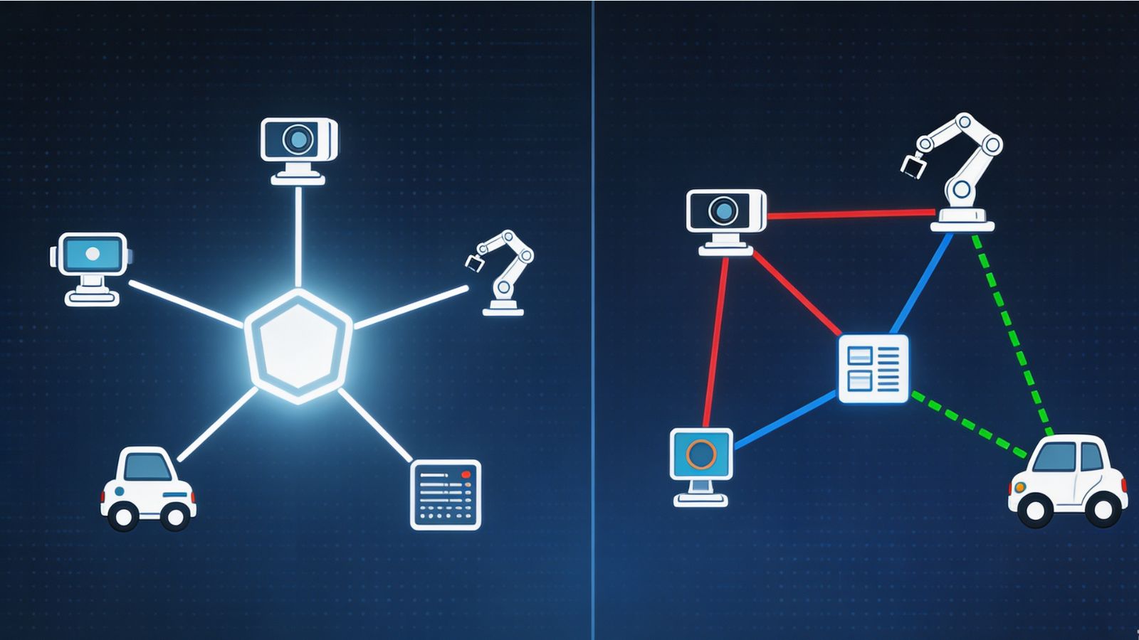
ROS 1 introduced a flexible communication model based on topics and services.
However, ROS 1 relied on a central component called the ROS Master.
The ROS Master helped nodes discover each other. When a node started, it registered information about available communication interfaces, allowing other nodes to locate and connect with it.
This architecture worked well for many research projects, but it introduced limitations:
A central discovery component became a dependency.
Large distributed systems were more difficult to manage.
Production environments often required additional reliability mechanisms.
ROS 2 redesigned the communication architecture by using DDS-based middleware.
DDS (Data Distribution Service) is an industry communication standard designed for distributed systems. In ROS 2, DDS provides functions such as discovery, data transport, and configurable Quality of Service (QoS) settings.
Unlike ROS 1, ROS 2 does not depend on a central ROS Master for node discovery. Instead, communication is based on a distributed discovery approach.
This architecture provides advantages such as:
Better support for multi-computer robotic systems.
More flexible communication configuration.
Improved scalability.
QoS controls for different application requirements.
For example, a live camera feed may prioritize low latency, while a robot control system may prioritize reliable message delivery.
ROS 2 also supports multiple DDS implementations, allowing projects to select middleware options according to technical requirements and deployment constraints.
One of the clearest examples of ROS integration is an autonomous mobile robot (AMR) used in warehouses.
A warehouse robot may be responsible for transporting goods between storage areas and packing stations. Although the task appears simple, the robot must coordinate many software functions.
The robot first collects information from sensors.
Typical inputs include:
Lidar scans for measuring distances.
Cameras for identifying objects and visual features.
IMU data for tracking movement.
Wheel encoder information for estimating motion.
These sensors publish data through ROS communication channels.
The robot must determine where it is inside the warehouse.
Localization systems combine:
Sensor measurements.
Existing maps.
Robot movement information.
The result is an estimate of the robot’s current position.
Without accurate localization, navigation software cannot determine the correct path.
The navigation system receives:
Current robot position.
Warehouse map information.
Obstacle data.
It then calculates a safe route.
For ROS 2 systems, Navigation2 (Nav2) provides components for localization, path planning, obstacle avoidance, and navigation behaviors.
The navigation system does not directly control every motor. Instead, it sends movement commands to lower-level controllers.
Motor controllers receive commands and convert them into physical movement.
The hardware layer manages:
Wheel speed.
Motor feedback.
Actuator communication.
This separation allows engineers to modify hardware without changing higher-level navigation software.
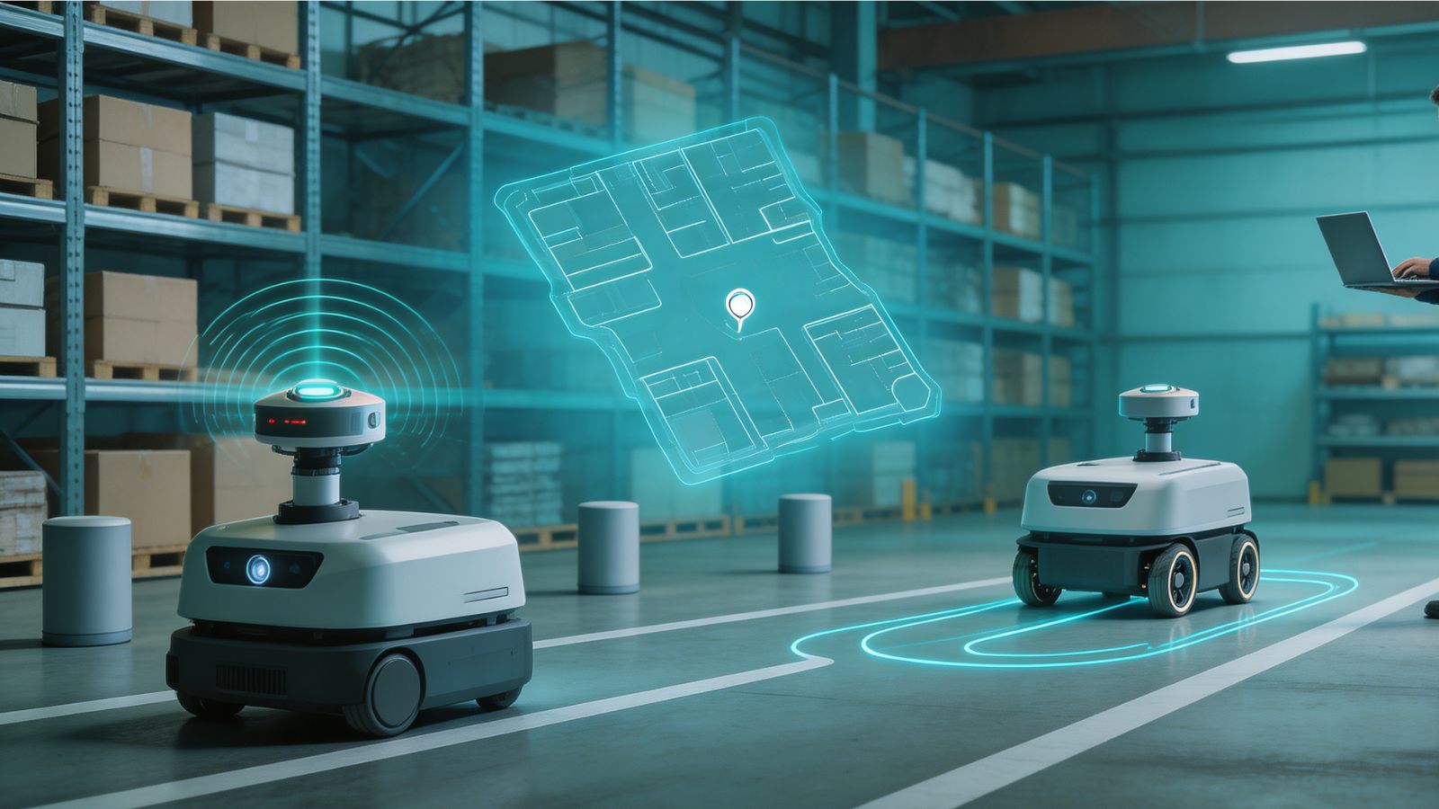
Developing a ROS-based robot is usually an iterative engineering process. Engineers rarely build the complete robot software system at once. Instead, they gradually integrate simulation, sensors, algorithms, and hardware.
A typical workflow includes several stages.
Before writing software, engineers first define the robot architecture.
They decide:
Which sensors are required.
Which functions should run as independent nodes.
How different components will exchange data.
Which parts require real-time performance.
For example, an autonomous delivery robot may separate:
Perception nodes for cameras and lidar.
Localization nodes for position estimation.
Navigation nodes for route planning.
Controller nodes for motor operation.
This separation makes debugging and future upgrades easier.
Many robotics teams begin development in simulation environments before using physical robots.
Simulation tools such as Gazebo allow engineers to test:
Robot movement.
Sensor behavior.
Navigation algorithms.
Environmental interaction.
A simulated robot can operate in a virtual warehouse or indoor environment before expensive hardware testing begins.
Simulation does not replace physical testing, because real robots experience factors that are difficult to model, such as sensor noise, mechanical wear, and unexpected obstacles. However, it reduces early development risks.
After basic software components are available, engineers connect real sensors.
Typical tasks include:
Checking whether camera data is published correctly.
Verifying lidar measurements.
Calibrating sensor positions.
Confirming coordinate transformations.
Tools such as RViz are commonly used to visualize:
Sensor outputs.
Robot position.
Maps.
Navigation paths.
Coordinate frames.
This stage is important because many robotics problems are not caused by algorithms but by incorrect sensor calibration or inconsistent data.
Once sensor data is available, engineers integrate higher-level functions.
Examples include:
Object detection.
Mapping.
Localization.
Navigation.
Manipulation planning.
Recorded sensor data can be used repeatedly during testing. Tools such as rosbag allow developers to capture ROS communication data and replay it later.
This helps engineers compare software versions and reproduce problems without repeatedly operating the physical robot.
After software performs reliably in testing environments, it can be deployed to real hardware.
Engineers then focus on:
Communication reliability.
Processing performance.
Battery usage.
Mechanical limitations.
Safety behavior.
A robot that works in a laboratory may still require significant optimization before operating in a warehouse, factory, or public environment.
One of ROS’s main strengths is its ability to connect different hardware components through common communication interfaces.
Robots often combine multiple sensors because no single sensor provides complete information.
Cameras provide visual information used for:
Object recognition.
Inspection tasks.
Human detection.
Visual navigation.
A typical camera workflow involves:
The camera driver receives image data.
The ROS interface publishes standardized image messages.
Computer vision algorithms process the images.
Other robot components use the results.
For example, a warehouse robot may use cameras to identify package locations or detect unexpected objects in its path.
Lidar sensors measure distances by analyzing reflected laser signals.
They are widely used for:
Mapping environments.
Detecting obstacles.
Supporting localization.
A navigation system may combine lidar measurements with a previously created map to estimate the robot’s location.
However, lidar alone usually does not provide enough information about object appearance. This is why many robots combine lidar with cameras.
A practical autonomous robot often uses sensor fusion.
For example:
Camera data helps identify objects.
Lidar provides accurate distance information.
IMU data helps estimate movement.
Wheel encoders provide motion feedback.
ROS allows these different data sources to be processed by separate modules while maintaining communication between them.
ROS is more than a communication framework. Its ecosystem includes tools that support simulation, debugging, visualization, hardware control, and deployment.
RViz is one of the most commonly used ROS development tools.
Engineers use RViz to inspect:
Robot models.
Sensor information.
Maps.
Navigation paths.
Coordinate transformations.
For example, if a robot fails to navigate correctly, an engineer can use RViz to check whether:
The map is correct.
The robot location estimate is accurate.
Sensor data is aligned properly.
This makes RViz an important debugging tool during development.
Simulation is essential for many robotics projects because physical testing can be expensive and time-consuming.
Gazebo allows developers to create virtual environments where they can test:
Robot movement.
Sensor behavior.
Navigation algorithms.
Physical interaction.
For example, a company developing a warehouse robot can test navigation software in a simulated warehouse layout before deploying the robot to a real facility.
Robots often produce large amounts of sensor data.
rosbag allows developers to record ROS messages and replay them later.
Common uses include:
Testing new algorithms with existing sensor data.
Investigating failures.
Comparing software versions.
For autonomous robots, this capability is valuable because developers can reproduce the same environmental conditions during testing.
A robot’s high-level software must eventually communicate with physical hardware.
ros2_control provides interfaces between ROS 2 systems and hardware components such as:
Motors.
Actuators.
Joint controllers.
This separation allows engineers to change hardware implementations while keeping higher-level software relatively unchanged.
For example, a mobile robot manufacturer may replace one motor controller with another while maintaining the same navigation software.
ROS provides communication infrastructure, but specialized frameworks provide higher-level robotic functions.
Two important examples are Navigation2 and MoveIt.
Navigation2 (Nav2) is a ROS 2 framework for mobile robot navigation.
It provides components for:
Localization.
Path planning.
Obstacle avoidance.
Motion control.
Recovery behaviors.
A warehouse robot using Nav2 may follow this process:
Receive a destination request.
Estimate its current position.
Calculate a safe route.
Avoid obstacles.
Send movement commands to controllers.
Nav2 does not create intelligence by itself. Instead, it provides a structured architecture that connects mapping, localization, planning, and control systems.
MoveIt is widely used for robotic arms and manipulation tasks.
It supports:
Motion planning.
Collision checking.
Joint trajectory generation.
Integration with perception systems.
For example, a manufacturing robot may use:
A camera to locate a component.
A perception system to estimate its position.
MoveIt to calculate arm movement.
Controllers to execute the motion.
This demonstrates how ROS connects perception, planning, and physical movement.
Although ROS provides powerful development tools, it does not eliminate the engineering challenges of robotics.
Developers must still address:
Some robotic applications require predictable response times.
Standard ROS communication may not automatically satisfy strict real-time requirements. Engineers may need specialized hardware, operating system configurations, or additional real-time techniques.
A robot operating in a factory or warehouse must handle:
Sensor failures.
Network interruptions.
Unexpected obstacles.
Hardware faults.
ROS provides communication mechanisms, but reliability depends on the overall system design.
For industrial or safety-critical applications, ROS is usually only one layer of a larger system.
Additional measures may include:
Safety controllers.
Emergency stop systems.
Hardware protection mechanisms.
Formal testing procedures.
ROS is valuable because it provides a common software structure for connecting complex robotic systems.
Its strongest contribution is not replacing robotics algorithms but making different technologies work together.
A modern robot may combine:
Sensors from different manufacturers.
Algorithms developed by different teams.
Hardware with different control systems.
ROS provides a communication framework that allows these parts to become a functioning system.
Today, ROS is widely used in:
Robotics research.
Education.
Autonomous mobile robots.
Industrial automation development.
Robotic manipulation systems.
However, successful commercial robots still require significant engineering beyond ROS, including hardware design, testing, safety validation, and production optimization.
Robot Operating System (ROS) provides a middleware foundation for building complex robotic systems by connecting sensors, software modules, and hardware controllers.
Its architecture allows robots to exchange information through nodes, topics, services, and actions while supporting different communication requirements. The transition from ROS 1 to ROS 2 introduced a more distributed architecture based on DDS middleware, improving support for larger and more complex robotic systems.
The ROS ecosystem extends beyond communication. Tools such as RViz, Gazebo, rosbag, ros2_control, Navigation2, and MoveIt support the practical workflow of designing, testing, and deploying robots.
ROS does not provide automatic intelligence or replace engineering decisions. Instead, it provides the software foundation that allows sensors, algorithms, and hardware components to operate as a coordinated robotic system.